TYPES
OF COUPLING
There are two types of coupling
RIGID COUPLING AND FLEXIBLE COUPLING RIGID TYPE COUPLING
This type of coupling has no flexibility or resilience,rigid couplings do not
accommodate misalignment hence it is necessary to be connected in good
alignment
Types of Rigid Couplings:-
1. Sleeve or muff coupling
2 . Clamp coupling,compression coupling or split muff coupling
3 . Flange coupling
1. Sleeve or muff coupling
2 . Clamp coupling,compression coupling or split muff coupling
3 . Flange coupling
Sleeve or muff coupling

It is the
simplest type of rigid coupling, made of cast iron. It consists of a
hollow cylinder whose inner diameter is the same as that of the shaft. It is
fitted over the ends of the two shafts by means of a Gib head key. The power is
transmitted from one haft to the other shaft by means of a key and a
sleeve. It is, therefore, necessary that all the
elements must be strong enough to transmit the torque.
Clamp coupling

Clamp coupling is sometimes called a compression coupling or a ribbed coupling. Clamp coupling is a modification and a improvement of the sleeve coupling. This coupling is made in two parts which are machined to fit the shaft and are finished off around the periphery and on both ends. The two halves of the coupling are clamped tightly against the surface of the shaft ends by through bolts and the entire torsional moment is transmitted entirely by friction.
Flange coupling

A flange
coupling usually applies to a coupling having two separate cast iron flanges.
Each flange is mounted on the shaft end and keyed to it. The faces are turned
up at right angle to the axis of the shaft. One of the flange has a projected
portion and the other flange has a corresponding recess. This helps to bring
the shafts into line and to maintain alignment. The two flanges are coupled
together by means of bolts and nuts. The flange coupling is adopted to heavy
loads and hence it is used on large shafting.
TYPES OF FLANGE COUPLING
1.Unprotected
type flange coupling
2.Protected
type flange coupling
3.Marine
type flange coupling
1) Unprotected type flange coupling:- In an unprotected type flange coupling each shaft is keyed to the boss of a flange with a counter sunk key, and the flange are coupled together by means of bolts. Generally, three, four or six bolts are used. The keys are staggered at right angle along the circumference of the shafts in order to divide the weakening effect caused by key ways.
2) Protected type flange coupling:- In a protected type flange coupling the protruding bolts and nuts are protected by flanges on the two halves of the coupling, in order to avoid danger to the workman.
3) Marine type flange coupling:- In a marine type flange coupling,
the flanges are forged integral with the shafts. The flanges are held together
by means of tapered headless bolts numbering from four to twelve depending upon
the diameter of shaft.
FLEXIBLE COUPLINGS
It is nearly impossible completely to eliminate all chance misalignment between
the shafts of separately built machines, and such misalignment of shafts always
leads to eventual failure of bearings or fatigue failure of shafts. The
relative position of the connected shafts, inaccurate at the outset due to
inevitable errors of manufacturing, is in course of time aggravated by
deformations caused by the working load, temperature fluctuations, the uneven
sinking of foundations or supports, etc. In such cases ineffective rigid
couplings are replaced by flexible couplings. Therefore the purpose of a
flexible coupling is to allow for imperfect alignment of two joining shafts, or
to absorb impact from the fluctuation of torsional moment or of angular speed.
These
couplings are rigid under torsion, but, allow the correction of errors in the
alignment of drive shafts.
OLDHAM TYPE COUPLING

Oldham can be used for any
velocities and loads and cause small additional loads and bearings.
The special advantage of this coupling is that it can be used for shafts which are not in alignment but whose axes are parallel up to the extent of 0.05 times the shaft diameter. By using this type of coupling minor axial alignment of shafts can be compensated.
The special advantage of this coupling is that it can be used for shafts which are not in alignment but whose axes are parallel up to the extent of 0.05 times the shaft diameter. By using this type of coupling minor axial alignment of shafts can be compensated.
The coupling consists of two flanges
keyed or secrewed to the respective shafts and the flanges have the slots on
the face surface. A cylindrical piece called disc with a tongue running across
each flat is present The tounges are at right angles to each other.
The Oldham joints allow rotational
movement between two parallel shafts, placed near to each other.
(Parallel mis-alignment). It is made up of two hubs, and a disk, which has two grooves, at right angles to each other.
During rotation, the grooves in the hubs slide into the grooves in the disk, thus correcting the mis-alignment.
(Parallel mis-alignment). It is made up of two hubs, and a disk, which has two grooves, at right angles to each other.
During rotation, the grooves in the hubs slide into the grooves in the disk, thus correcting the mis-alignment.
The result of this is that the drive
shaft and driven shaft turn at the same speed.
BELLOW COUPLING

These couplings link a torsional
rigidity, high torque, mis-alignment and high rotational speeds. They are light
in weight, they have a large range of applications and they are very good value
for money.
They are made up of two hubs which are mounted on the
shafts, and a bellows, which whilst being rigid under torsion, has the
flexibility in a longitudinal sense to correct any mis-alignments. The bellows
is welded onto the hubs. These couplings are capable of very high rotational
speeds. At high speed, the least eccentricity would lead very high levels of
vibration which could be detrimental to the system as a whole.
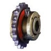
BUSHED
PIN TYPE COUPLING

The Cone Ring Couplings unique flexible element
comprises tapered rubber rings mounted on steel pins. The rubber rings absorb
commonly encountered misalignment, shock and vibration.
JAW TYPE COUPLING or SPIDER COUPLING

spider
three
jaw
multi jaw
|
Economical, resilient coupling not requiring
lubrication. The jaw coupling is torsionally flexible and designed for positive
torque transmission. Jaw couplings are puncture proof , operational vibrations
and shock are efficiently attenuated and reduced
there are
three jaw coupling and multi jaw coupling,
SPRING GRIND COUPLING

Grid
couplings are designed for versatility. Common hubs and grids are used within a
given size range for both horizontal and vertical split cover models. Grid
installation and replacement can be done without moving the hubs making
maintenance very easy.

Chain couplings
are an economical shaft connection with easy disconnection. Chain couplings
offer maximum efficiency in connecting two shafts for transmission of power.
HRC COUPLING

The HRC is a
general purpose Flexible coupling available in eight sizes in taper bush style
or pilot bore.
GEAR COUPLING

With the
capacity of handling heavy loads, gear couplings are much smaller and lighter
than other types of couplings. Noise and vibrations are hardly produced even in
high speed operation
TYRE COUPLING
Tyre
Coupling to compensate for large amounts of shock loading the backlash, as well
as both parallel and axial misalignment.

universal joints are not true flexible
couplings but can transmit high angular misalignment, up to 45 degrees with a
single joint or 90 degrees with a double joint/pair of single joints. They are
available in single, double and telescopic versions for shafts 6 to 50m.
Universal joints with plain bearings suit speeds below 1000 r/min and
lubrication is needed, usually provided by an enclosing gaiter. For higher
speeds universal joints with needle roller bearings are used.
TORQUE LIMITORS
The Torque Limiter has been designed to protect drive systems from
unnecessary overload. When too much torque is transmitted though a drive, the
Torque Limiter automatically slips on its shaft when a predetermined torque
level is reached
UNIVERSAL JOINTS